Hydraulic pressure control determines how reliably a machine turns pump output into useful, repeatable movement. In an excavator, pressurized oil must lift a loaded boom without sudden drops, sluggish response, or wasted energy. Small fluctuations can affect cycle time, heat the oil, and accelerate wear on seals, hoses, and valves. Details matter.
The question “what is the importance of hydraulic pressure control” reaches beyond performance. Correct pressure helps protect components, maintain predictable force, and support safe operation as loads change. Relief valves, regulators, sensors, and clean filters each contribute, but no single part guarantees good control. System design and operating conditions matter too. Control matters.
This guide explains how pressure control works, where it affects efficiency and reliability, and which warning signs deserve attention. A gauge that swings sharply, a cylinder that drifts, or unusually hot oil can point to a problem. They do not prove its cause. Diagnosis should follow equipment specifications and qualified service procedures, rather than guesswork or a quick adjustment. That distinction is easy to overlook.
Pressure targets are not universal. A setting that suits one circuit may damage another, and raising pressure is not a sound shortcut to stronger performance. The practical goal is stable pressure matched to the machine, load, and task. Hydraulic systems are not always tidy. Leaks, temperature, contamination, and worn parts can interact, so troubleshooting takes patience. Understanding these limits makes pressure control more than a technical setting; it supports dependable equipment use.
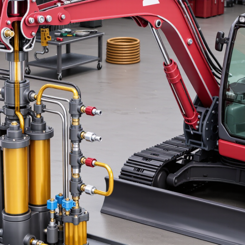
What Hydraulic Pressure Control Does in a Fluid Power System
Hydraulic pressure control determines how much force a fluid power system can deliver and helps keep that force within safe limits. The pump moves fluid; resistance from a cylinder or motor creates pressure. A pressure-control valve responds to that condition, rather than simply making the pump “stronger.” Small changes matter.
A relief valve limits maximum pressure by opening when the system exceeds its set point, directing fluid back to the reservoir. A pressure-reducing valve maintains a lower pressure in a branch circuit, such as one serving a clamp while another actuator needs more force. These controls help protect hoses, seals, and cylinders from excessive loads. They also make machine behavior more consistent when the load changes.
A gauge near the valve can show whether operating pressure matches the specified setting. If the reading repeatedly climbs, the cause may be a blocked line, an overloaded actuator, or a valve that needs inspection. Pressure control does not correct every problem. For example, a relief valve that opens often can turn energy into heat, so the oil may become hotter than expected. Settings need review as components wear or operating conditions change. The correct value is not always obvious. A trained technician should verify adjustments against the equipment specifications.
How Relief, Reducing, and Sequence Valves Regulate Pressure
What Is the Importance of Hydraulic Pressure Control?
How Relief, Reducing, and Sequence Valves Regulate Pressure
Hydraulic pressure control keeps machinery within its intended operating range. Without it, pressure spikes can strain hoses, seals, and cylinders. A relief valve limits maximum system pressure by opening a path to the reservoir when pressure exceeds its setting. You may hear the valve open during a sudden load change. That sound can signal normal protection, but repeated opening may indicate a mismatch or fault.
A reducing valve serves a different purpose. It maintains lower pressure in a branch circuit while the main system operates at a higher level. For example, a clamping cylinder may need less force than the machine’s lifting cylinder. The reducing valve helps prevent excessive clamping force. Its setting still needs verification under real operating conditions; a gauge reading at rest may not tell the whole story.
A sequence valve directs flow to another actuator after pressure reaches a preset point. A press might clamp a workpiece before its ram begins moving. The sequence valve makes that order possible. Not always perfectly. Friction, changing loads, and valve response can affect timing, so observe the machine through a full cycle. Record pressure readings and inspect for heat, leaks, or unexpected movement. These details help distinguish a control problem from normal variation.
What Is the Importance of Hydraulic Pressure Control? — How Relief, Reducing, and Sequence Valves Regulate Pressure
| Valve Type |
Typical Normal State |
How It Regulates Pressure |
Typical Function |
Common Applications |
Key Design Consideration |
| Pressure relief valve |
Normally closed |
Opens when inlet pressure reaches its set point, diverting flow to the reservoir or another low-pressure path to limit system pressure. |
Protects the pump, lines, and components from excessive pressure. |
System overpressure protection; pump outlet protection; limiting pressure in a hydraulic circuit. |
Set the valve in accordance with the system’s pressure ratings and operating requirements. Account for pressure rise as flow through the valve increases. |
| Pressure-reducing valve |
Typically normally open |
Senses downstream pressure and throttles flow to maintain a lower pressure in a branch of the circuit. |
Provides a controlled lower-pressure zone while the main circuit operates at a higher pressure. |
Low-pressure clamps, auxiliary actuators, and circuits requiring different pressure levels. |
Check the valve’s flow capacity and pressure range. Many designs require a separate drain connection; follow the valve’s hydraulic schematic. |
| Pressure sequence valve |
Typically normally closed |
Opens when inlet pressure reaches its set point, allowing flow to a secondary circuit after the primary circuit reaches the required pressure. |
Controls the order in which hydraulic operations occur. |
Sequential cylinder movements; clamping before machining; staged actuator operations. |
Use an appropriate drain arrangement where required, and account for the pressure needed to operate the downstream circuit. |
| Why pressure control matters |
Applies throughout the circuit |
Coordinates maximum pressure, branch pressure, and pressure-dependent operating order. |
Helps protect equipment, support repeatable operation, and match pressure to the task. |
Mobile and industrial hydraulic systems, presses, machine tools, and material-handling equipment. |
Correct sizing, setting, installation, filtration, and maintenance are essential; verify the circuit design and component specifications. |
Note: Valve behavior and porting can vary by design. Confirm pressure settings, flow limits, drain requirements, and installation details against the hydraulic circuit diagram and the component manufacturer’s specifications.
How to Set Pressure Within Component Ratings and System Limits
Hydraulic pressure should be set by the weakest component in the circuit, not by the pump’s maximum capability. Check the ratings for hoses, fittings, cylinders, valves, and seals, then set the relief valve at or below the lowest applicable limit. ISO 4413:2010 requires hydraulic components to operate within their specified limits and calls for protection against excessive pressure. That principle matters during real load changes: a cylinder that stalls against a fixture can create a sharp pressure rise.
Use a calibrated gauge near the pressure source and, where needed, measure pressure at the actuator under working load. NIOSH Publication 89-101 warns that high-pressure fluid injection injuries can occur at pressures as low as 100 psi. A pinhole leak may look harmless. Keep hands away; use cardboard to locate suspected leaks, and depressurize the circuit before inspection. Small leaks matter. Record the relief setting, gauge reading, and component ratings so later adjustments can be checked against the same limits. One detail is easy to miss: readings taken at idle may not reveal pressure spikes during a stalled or rapidly changing load. Recheck after maintenance, and leave a practical margin below component ratings; the exact margin depends on the system design and operating conditions.
Safety Requirements for Hydraulic Systems Under ISO 4413:2010
Hydraulic pressure control is a safety function, not just a way to make a machine perform smoothly. ISO 4413:2010 sets safety requirements for hydraulic fluid power systems and their components. It calls for hazards to be identified and risks reduced through design, protective measures, and clear information for use. In practice, designers need to consider the maximum pressure a circuit can experience, including pressure spikes when a valve closes or a load suddenly shifts.
Pressure-relief devices should be suitable for the circuit and arranged so excess pressure can be safely limited. They do not replace sound component selection or careful installation. Hoses, fittings, cylinders, and other parts must be rated for expected pressures and operating conditions. Stored pressure matters, too. A machine may seem stopped while an accumulator or trapped fluid still holds energy. Provide a safe means to isolate and release that energy before maintenance, and make the procedure clear to technicians. A gauge helps, but it cannot prove every section is depressurized. That detail is easy to miss.
Operators need understandable warnings and instructions, while maintenance staff need access to reliable system information. Practical reviews should include foreseeable misuse, inspection needs, and the consequences of a failed component. The standard provides a framework, not a substitute for assessing the actual machine and its environment. Check the applicable edition and involve competent hydraulic and safety professionals when validating a design.
What Is the Importance of Hydraulic Pressure Control?
Pressure control helps prevent excessive pressure, protect components, and reduce hazards during operation. This illustrative response shows pressure rising during a load change and settling near the operating target. The values are example test data, not limits specified by ISO 4413:2010; system pressure limits must be determined from the actual design and risk assessment.
Typical Industrial Systems Operate at 100–350 bar, Depending on Duty
Hydraulic systems commonly operate between 100 and 350 bar, but the right pressure depends on the work. A lifting platform may need a different setting from a compact clamping circuit. Pressure creates force; flow largely affects how quickly an actuator moves. Treating pressure as a simple “more is better” setting can waste energy and strain seals, hoses, and pump components.
The duty matters. A system that handles steady loads may need less pressure than one facing brief, heavy resistance. Check the machine’s operating requirements and component ratings before adjusting settings. A pressure gauge near the circuit can reveal changes that are easy to miss during routine operation. Watch for slow movement, unusual heat, or leaks around fittings. Small clues count.
Relief valves help limit excessive pressure, but they do not replace correct setup or inspection. For example, a cylinder that stalls under load may have a pressure issue, but restricted flow or internal leakage could also be involved. Diagnosis takes care. In practice, pressure readings can fluctuate with temperature and load, so one reading may not tell the whole story. That part is easy to overlook. Keep records under consistent operating conditions, and compare readings with the system’s specifications.
Conclusion
Understanding what is the importance of hydraulic pressure control begins with recognizing its role in keeping a fluid power system safe, stable, and efficient. Pressure control helps match the force delivered by hydraulic equipment to the task, protects components from excessive loads, and supports predictable operation. Relief valves limit maximum pressure, reducing valves maintain lower pressure in selected circuits, and sequence valves coordinate operations by allowing one function to begin after another reaches a set pressure.
Pressure settings should remain within the ratings of every connected component and the limits of the overall system. They should be established and checked using suitable procedures, with attention to operating conditions and maintenance needs. ISO 4413:2010 provides safety principles for hydraulic systems, including measures to reduce risks from pressure, stored energy, and unexpected movement. Many industrial systems operate in the range of 100–350 bar, depending on their duty, but the correct pressure is determined by the equipment design and application.

 Aksurion Hydraulic